|
|||||||||||||||||||||||||
|
|||||||||||||||||||||||||
| Beam
distribution on the collimators |
||||||||||||||||||||||||||||||||||||||||||
|
|
||||||||||||||||||||||||||||||||||||||||||
| In this page, the particle distributions on the LHC collimators can be found for various accident scenario cases at injection (450 GeV) and at top (7 TeV). These distributions should be used as input for the FLUKA simulations of energy deposition in the collimator jaws of IR7. For each considered cases, the matched beam distributions are given at the impact locations on the collimator. "Matched" means that the bunch particles have to correct transvrerse phase-space distribution (x, x', y, y') expected at the LHC. This is suitable for the FLUKA simulations that contains all the magnetic elements of IR7. The optics parameters are given at the beginning of the collimators and hence are suitable for the FLUKA tracking inside the collimator and in the downstream beam line. Different failure scenarios are considered for injection and collision cases, as presented below. It is noted that the cases to be considered are several. As a guideline for the first simulations to perform, a priority list is provided in order to select the scenarios which are (expected) to be the most interesting. Additional beam distributions at other locations then the ones considered below can be obtained upon request to Stefano Redaelli.
(1) Injection energy (450 GeV) The worst considered scenario is the case of a
full injection batch impacting on a primary or
a secondary collimator. Since the injection form the SPS is done
in the vertical plane, injection errors are likely going to generated
large vertical oscillations. However, the cases
of horizontal and skew errors will also be considered.
Horizontal and vertical beam distributions with
impact parameters of 1 sigma and
5 sigmas are considered for various collimators.
For a typical beam size at 450 GeV of ~1mm, this corresponds to
impact parameters of approximately 1 mm and 5
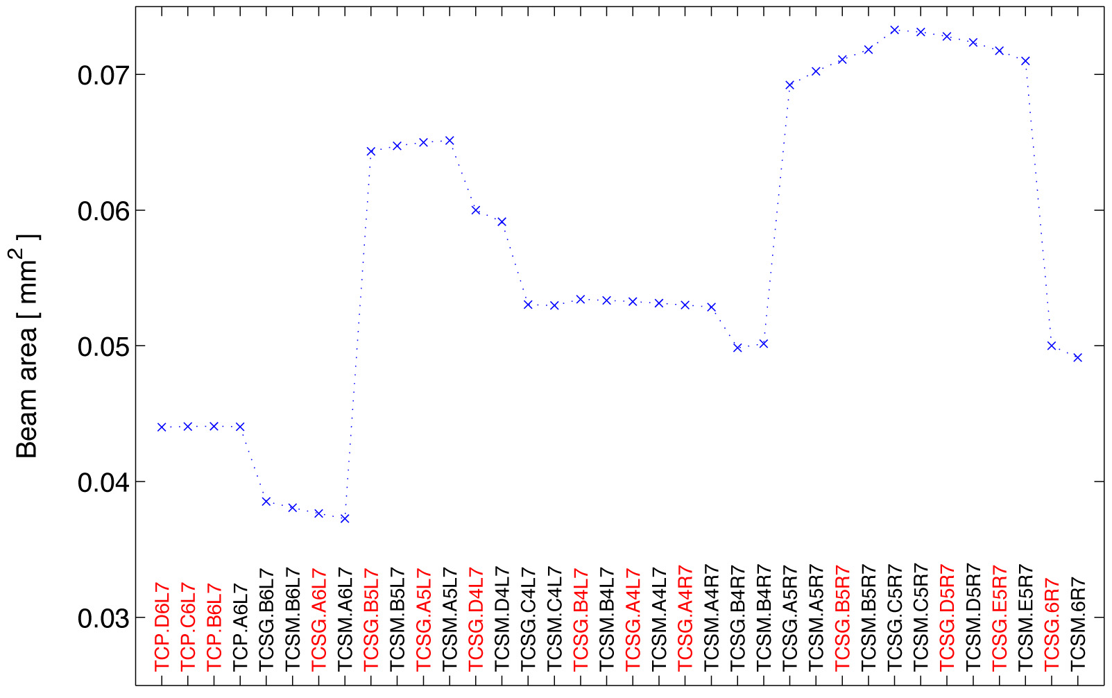
mm. The nominal gap settings of the collimators are assumed:
6 sigmas for the TCP's and 7 sigmas for the TCS's. The particle
distribution are given at the beginning of each
collimator. Parameters of beam distributions
Beam distributions (uncompress with "bunzip2 FileName.bz2")
Collimator setting
Priority list
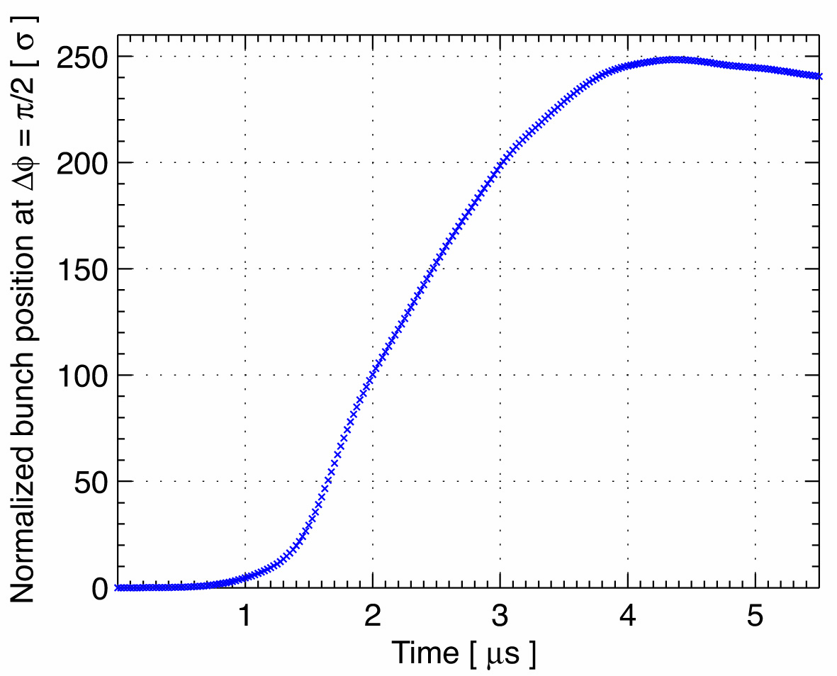
(2) Collision energy (7 TeV) The considered scenario is a wrong firing of the horizontal extraction kicker with nominal 7 TeV beam stored in the LHC. In this case, the various bunches of the beam experience different kicks during the kicker field ramp and are spread downstream of the kicker with different amplitudes. The normalized horizontal position of the bunch centroid versus time at a pi/2 phase advance downstream of the kicker is shown in the following graph.
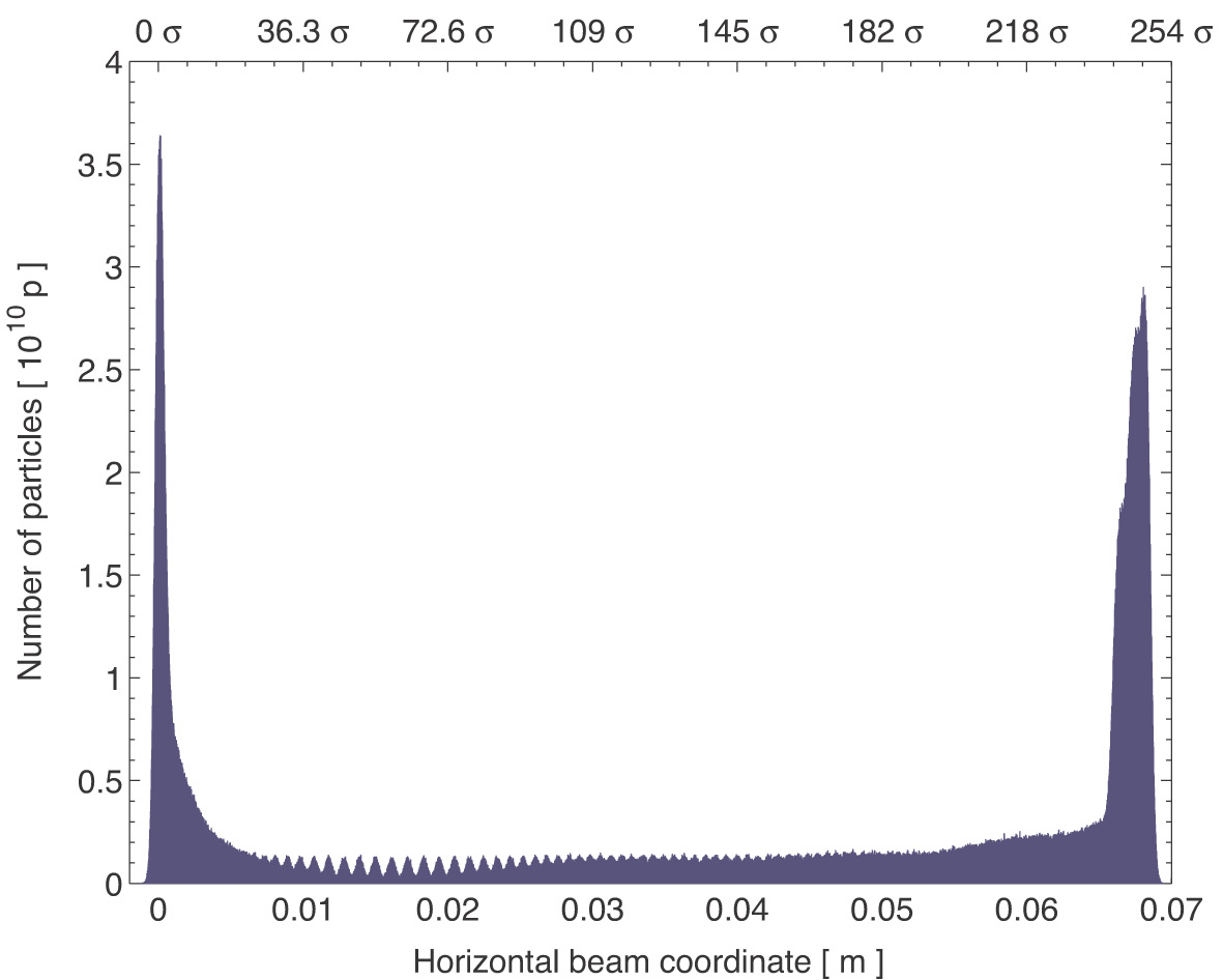
The kicker mis-firing is modelled by using the measured rising time and by assuming a re-triggering time of 700 ns (see Chapter 18 of the LHC design report). The extreme cases of first and last kicker module are simulated and the worst case is considered. The bunch amplitudes versus time are calculated at the worst location downstream of the kicker, i.e. at a pi/2 phase advance downstream of the kicker. Since various operation consitions must be considered, it is assumed that any collimator may be at a pi/2 phase advance from the kicker when the mis-firing occurs. Correspondingly to the previous graph, the expected particle distribution versus x coordinate is given in the following plot. The distribution of hitting particles depend on the local optics parameters. As an example, the case of the first primary collimator (TCP.C6L7.B1) is considered. Here, it assumed that this collimator is at a pi/2 phase advance downstream of the kicker.
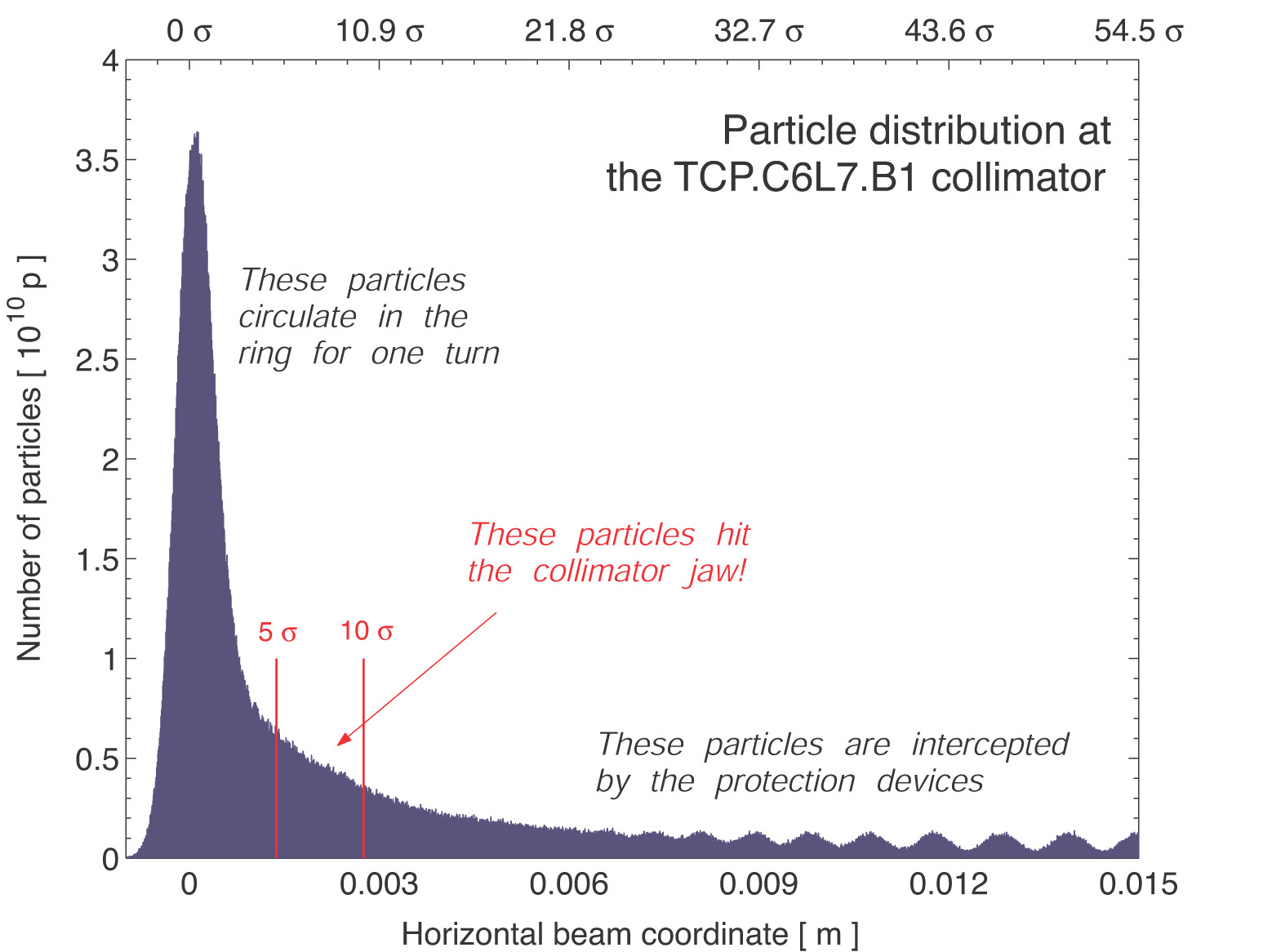
In order to calculate the number of particles that
can hit the collimator jaw, it is assumed that particles with amplitude
above 10 sigmas are efficiently absorbed
by the dedicated protection devices (TCDQ) whereas the
particles with amplitude below 10 sigmas circulates
in the ring for one full turn before they are extracted at the next
passage trhough the kicker. It is assumed that the collimators
may be set with a depth of 5 sigmas (the nominal
settings of primary and secondary collimators are 6 and 7 sigma
but some operational margin is assumed). Therefore, particles
with amplitudes between 5 and 10 sigma might hit the collimator.
Since various operation consitions must be considered, it is assumed that any collimator may be at a pi/2 phase advance from the kicker. Therefore, any collimator can be hit by mis-kicker particles of amplitudes between 5 and 10 sigmas. The matched particle distributions should be generated at each collimator locations. In practise, only the case of horizontal collimators seems relevant. The skew collimators can also be hit by particle and, depending on their location, the corresponding effect could be relevant. This should be investigated. It is noted that, since the collimators can be located either at at pi/2 or at 3/2pi phase advance from the kicker, both collimator jaws can be hit by mis-kicked bunches. One case or the other can be obtained by reflecting the particle distribution which are given below. In the following input files, bunches with amplitudes
between 1.5 sigmas and 15 sigmas have only been considered because
bunches outside this range do not significantly contribute to the
particles that might hit the collimator jaws. For each bunch, a
Gaussian distribution is assumed. Parameters of beam distributions
Beam distributions (uncompress with "bunzip2 FileName.bz2") |
||||||||||||||||||||||||||||||||||||||||||
|
|
||||||||||||||||||||||||||||||||||||||||||
| S. Redaelli, Thursday, 05. April 2012 11:07 +0200 |